wiki:design_construction
Table of Contents
Design and Construction of dilution refrigerators
Modern dilution refrigerator techniques are based on the La Jolla principles and methods, and the Grenoble design, described in Cryogenics books and several original articles on dilution refrigeration.
There exist many different types of dilution refrigerators, in terms of lowest working temperature and cooling power, size of the machine, and additional constraints (possibility to immerse the sample in the mixing chamber, use in a neutron or X-ray beam, in ultra-high vacuum etc.).
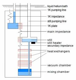
Classical ("wet") dilution refrigerators
- Small dilution refrigerators (“la Jolla” style) have diameters of a few cm, their 3He flow rate is ~10 to 50 µmol/sec. They are often used as “inserts” in a liquid helium dewar . Due to their small size, the heat exchangers have a small total area, and heat leaks make it difficult to reach temperatures below 10 mK.
- Larger refrigerators with heat exchangers of typical diameters larger than 10 cm (“Grenoble design”) can reach temperatures on the order of 2 mK, with flow rates of 100 µmol/s. They can also provide large cooling power, with flow rates up to 10 mmol/s, obviously at higher working temperatures.
- Cooling power at the MC is given by the simple expression
- Very large dilution refrigerators (“CERN design”) are used to cool targets in particle physics, or other high power applications.
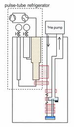
Pulse-tube based ("dry") dilution refrigerators
- Dilution refrigerators can be pre-cooled by Cryo-Coolers, thus suppressing the helium bath. These “dry fridges” are similar to those described above.
- The first units used Gifford Mac-Mahon coolers, but the large level of vibration end up making these machines a curiosity. Pulse-tube machines have a much lower vibration level.
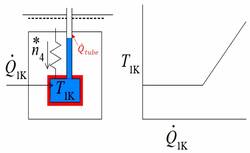
- When pulse-tube coolers reached temperatures below 4 K, several groups developed pulse-tube dilution units. The machine must be carefully optimized, the thermodynamics limit for condensation being very close without a 1K pot. Contrarily to the classical liquid helium bath, the temperature of the “4K stage” of the pulste-tube cryocoolers increases rapidly with the applied power (essentially the gheat of condensation of the 3He).
- The possibility to obtain large “additional cooling power” at intermediate temperatures (between 4K and 50 K stages) strongly reduces the heat load on the 4K stage, maintaining a lower temperature, and also allowing a rapid condensation of the mixture.
- The success of this type of machines results therefore from a combination of the low temperatures achieved by modern pulse-tube cryocoolers, their low vibrations, and the additional cooling power mentioned above.
"1K pot" and "no 1K pot" dilution refrigerators
- The incoming 3He has to be pre-cooled to relatively low temperatures to satisfy the thermodynamic requirement that the enthalpy of the 3He gas leaving the still, must be higher than the enthalpy of the 3He gas entering the dilution set-up, just before the thermalization on the still, if any cooling is to be obtained.
- A separate cooling stage, the “1K pot” , is traditionally used in “wet refrigerators”. A pot filled with helium from the helium bath through a capillary, and eventually a cold valve, is pumped to about 1.4 K through a pumping line, by means of a mechanical pump.
- The 1K pot is often a source of problems, the feeding capillary may get blocked by dust, or by small ice or solid nitrogen, argon or oil particles. Different systems of filters have been tried, but the best is to check the bath is leak-free to the room, and that clean helium storage Dewars are used.
- The design of 1K pots as well as systems pre-cooled without 1K pot (compressed 3He) is discussed in several publications:
The 3He condensation line
The "still"
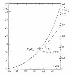
- The still (short for distillator), also called evaporator, is used to remove selectively 3He from the 3He-4He mixture of the refrigerator. This is typically done by pumping at pressures on the order of 10 Pa for flow rates on the order of 150 µmol/sec, easily provided by turbomolecular, roots, or diffusion pumps.
- The still operates optimally at temperatures of 0.7 K, as seen in the graph. For a given flow rate, this sets the required pumping speed, i.e. the choice of the pump. At higher pressures, the 4He contribution to the flow rate increases, creating a parasitic 4He circulation which loads the condensation stage at the refrigerator inlet. Film burners or diaphragms alleviate this problem.
- The 3He concentration in the still is very low, typically less than 1% (depends on temperature). A constriction (of typical diameters below 1 to 2 mm) in the tubes coming from the continuous heat exchanger, in the vicinity of the still, severely limits the 3He Flow rate, an important observation due to G. Frossati. The effect can explained by a “roton wind” against the 3He particles.
- The still must have a relatively large volume, typically ~3-30 cm3. The mixture level in the still can thus change, compensating for the variations in the total amount of mixture condensed inside the refrigerator. The variations arise because of changes in the condensation pressure when the flow rate is changed, for instance.
- The still plays an important role: the 3He flow rate of the dilution refrigerator, and hence the cooling power available at the level of the mixing chamber, is mainly determined by the power applied to the still.
The Continuous heat exchanger
The Step ("discrete") heat exchangers
The Mixing Chamber
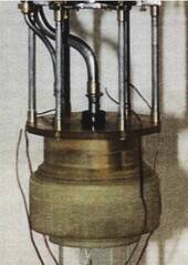
- The mixing chamber can be made out of copper, stainless steel, plastics, etc. Plastic MC are used in the presence of varying magnetic fields, to avoid eddy current heating.
- The MC volume is chosen typically from a few cm3 (in very small refrigerators) to several liters (very large flow rate machines). Modern refrigerators including a large sintered silver heat exchange in the mixing chamber, have volumes of about 100-400 cm3.
Cooling power of Dilution Refrigerators
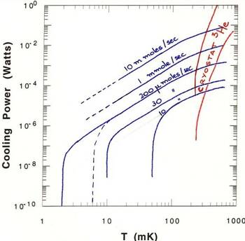
- The figure shows the cooling power of different types of dilution refrigerators.
- Cooling power = 82 dn3/dt T^2. This standard formula relates the cooling power in watts to the flow rate expressed in moles/sec (dn3/dt).
It is applicable for temperature T>3 Tmin, where Tmin is the base temperature of the dilution refrigerator (no applied external power).
- Depending on the typical size of the machine (see above), different flow rates can be achieved, and hence different cooling powers.
- The performance of refrigerators optimized for very low temperatures is indicated by dashed lines.
- Pumped 3He refrigerators have larger cooling powers that dilution refrigerators for T>0.35 K. The are also significantly more user friendly…
Troubleshooting Dilution Refrigerators
- 1 K pot hot, pressure is low. Filling capillary blocked. Remove LHe so that the bath level is below the intake, keep 4He pressure in Pot above bath pressure. Having a heater on the 1K pot capillary can help, applying heat pulses…
- High inlet pressure. Air? Hydrogen? Water?
- Low still pressure. Still empty? Check T_still vs. P_still ! If there is no liquid, the pressure j
- is low, but the temperature is high.
- No cooling power. Interface level in MC? Heat leak to MC? Apply heat and check cooling power at higher temperatures. 3He/4He ratio OK?
- Heating spikes, temperature oscillations. Superfluid leak to Vacuum can? Check for spikes in the vaucum can pressure.
wiki/design_construction.txt · Last modified: 2022/12/15 17:46 by henri.godfrin@neel.cnrs.fr

